A register in an FPGA is a storage element that can hold one bit or more. In VHDL there are two methods of inferring registers. The most common method is to use a signal that updates its value at the rising edge of a clock. The other method is to use a VHDL variable. Both methods have their advantages and disadvantages.
Why use variables instead of signals for declaring registers?
There are two main reasons for choosing variables over signals when making registers. The first is that a variable value is updated immediately when the variable is assigned, as opposed to a signal which has a delay of at least a delta cycle. The delta cycle delay means that an updated value of a signal can’t be used in the same iteration of the process, i.e., the signal output is still the old value until the process is called again at least a delta cycle later. If a clocked register shall be updated with the result of a calculation within a single clock period, it may be wise with respect to readability to use a variable to hold intermediate values at each step of the calculation instead of using an additional combinatorial process. If that is the case it may be the best solution to use a variable to make the register instead of using both a signal and a variable, if the result shall be used only within that process.
The following two code snippets show two designs that are identical for both RTL and gate level (after synthesis). The first example uses two processes and three signals. The second example uses a single register variable to get the same result.
...
architecture rtl of design is
    ...
    signal result_comb_intermediate : std_logic;
    signal result_comb_final        : std_logic;
    signal result_reg               : std_logic;
    ...
begin

p_comb:
process (all)
begin
  result_comb_intermediate <= input_0 xor '1';
  result_comb_final        <= result_comb_intermediate and input_1;
end process p_comb;

p_seq:
process (clk, arst)
begin
    if arst = '1' then
        result_reg <= '0';
        output     <= '0';
    elsif rising_edge(clk) then
        if input_2 = '1' then
          -- Use result of calculation as output
          output <= result_reg;
        else
          -- Store calculation result
          result_reg <= result_comb_final;
        end if;
    end if;
end process p_seq;
We assume that the inputs input_0, input_1 and input_2 are all synchronized to clk. When input_0 changes, the process p_comb is triggered and result_comb_intermediate is updated. A delta cycle later, p_comb is triggered again because of the updated signal value. result_comb_final is then updated and ready before the next rising edge of clk. As can be seen from the code snippet below, the use of a register variable saves a lot of code lines and clutter in this case.
p_seq:
process (clk, arst)
    variable vr_calc : std_logic;
begin
    if arst = '1' then
        vr_calc := '0';
        output  <= '0';
    elsif rising_edge(clk) then
        if input_2 = '1' then
          -- Use result of calculation as output
          output <= vr_calc;
        else
          -- Calculate using input
          vr_calc:= input_0 xor '1';
          vr_calc:= vr_calc and input_1;
        end if;
    end if;
end process p_seq;
This brings us to the other main reason why variables are useful: encapsulation. When designing a module with multiple processes in VHDL it is required to use signals to allow the processes to communicate. Within each process there may be registers that hold values that are only relevant for that process. Developers often use signals to make these registers, but that has the risk of cluttering the signal declarations in the architecture (as seen in the first example). What signals are used for inter-process communication and what signals are only used for registers within a single process? This is a case where register variables are very useful because the scope of a variable is just the process where it is declared. When using register variables, it is not possible to misunderstand where the register value is useful. It’s then also crystal clear that all signals are used for inter-process communication. The code snippet below shows a buffer register implemented as a variable.
p_regvar:
process (clk, arst)
     variable vr_buf : std_logic;
begin
    if arst = '1' then
         vr_buf  := '0';
         output  <= '0';
    elsif rising_edge(clk) then
        -- Assigning buffer to output
        output <= vr_buf;

        -- Assign input to buffer
        vr_buf := input;
    end if;
end process p_regvar;
Note that the register variable has the prefix “vr_” to indicate that it is a variable, and that the intention of the developer is to make a register. This is just a code convention. Another convention could be to name it v_buf_reg or something similar to indicate with the prefix that it is a variable and with a suffix that it is a register.
The following figure shows this synthesized for an AMD FPGA:
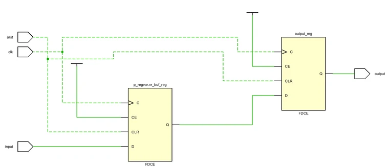
This is as expected. The vr_buf variable is a register, as well as the output signal.
Things to keep in mind when using register variables
There are some things that one must remember when using register variables in order to get the expected result. Note the ordering of the assignments in the previous code snippet. The output must receive the value of vr_buf before vr_buf receives the input value, otherwise the input is assigned directly to the output.
The synthesis result is shown in the following figure:
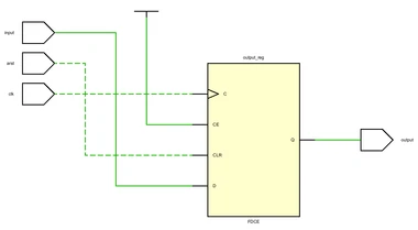
As expected, the wrong order of statements results in only a single register. See the difference in the code snippet below where the buffer is implemented as a signal.
p_regsig:
process (clk, arst)
begin
    if arst = '1' then
        buf    <= '0';
        output <= '0';
    elsif rising_edge(clk) then
        -- Assign input to buffer
        buf <= input;

        -- Assing buffer to output
        output <= buf;
    end if;
end process p_regsig;
Here the ordering of the assignments does not matter because the output of the signal buf is still the old value in this iteration of the process. The new value will not be assigned to output before the next rising edge of clk.
When using register variables and taking advantage of the immediate update of value to perform a series of operations in a single clock period, it is very important to be mindful of the depth of the generated combinatorial path. Each statement will contribute to the depth of the combinatorial path and too many operations in a single clock period will cause trouble with timing closure of the design. How many statements are too many? That depends on the FPGA device and the desired clock frequency.
There is an issue regarding simulation of register variables. During simulation of VHDL-2008 it is possible to use hierarchical references to access signals at lower levels in the hierarchy, either for probing or for forcing signal values. This unfortunately doesn’t work for variables at the moment.
Final Words
Using register variables instead of register signals can help with encapsulation and with readability when performing multiple actions in a single clock period. One must be aware of how variables differ from a signal to get the expected behavior and resource usage from the design, but if used properly register variables can be a very powerful tool to increase readability and functionality of a design.