Introduction
USB BC 1.2 stands for “USB Battery Charging 1.2,” established as a standard by the USB-IF Association in October 2010. USB BC had a preceding version, USB BC 1.1, which was unveiled in 2009.
In adherence to the USB-IF Battery Charging Specification, precise current limits and protocols are established. These specifications facilitate portable devices to extract power from source ports such as host/hub ports and dedicated chargers, exceeding the limit of 500 mA for USB 2.0 ports or 900 mA for USB 3.0 ports.
USB data lines (D+/D-) are used for USB BC 1.2 detection and handshaking process. Upon successful detection and confirmation of BC 1.2 support, the USB port supplies a current of 1.5 A to expedite the charging process. Both the portable device and the USB host or hub must possess BC 1.2 support, involving the detection of data lines. After finishing and confirming that BC 1.2 detection is supported, the USB port provides 1.5 A for charging.
USB Type-C ports follow a separate procedure using Channel Configuration (CC1/CC2) pins. Nevertheless, these ports still retain the ability to engage in BC 1.2 detection protocols. The device itself is responsible for detecting the current delivering capability of the source port using its preferred method and adjusting the current draw accordingly.
Table 1- USB Power Delivering Capabilities:
| Specification | Maximum Voltage | Maximum Current | Maximum Power |
| USB 2.0 | 5 V | 500 mA | 2.5 W |
| USB 3.0/USB 3.1 | 5 V | 900 mA | 4.5 W |
| USB BC 1.2 | 5 V | 1.5 A | 7.5 W |
| USB Type-C 1.2 | 5 V | 3 A | 15 W |
| USB Power Delivery 3.0 | 20 V | 5 A | 100 W |
Common USB BC 1.2 Ports
Within the USB BC 1.2 standard, three distinct USB port categories are described alongside the introduction of two primary designations: Charging and Downstream. Termed as a “charging” port, it denotes the supply of currents surpassing 500 mA, while a “downstream” port indicates data transmission conforming to either USB 2.0 or USB 3.0 standards. Moreover, the BC 1.2 specification precisely defines how each port must be identified by the end device and details the protocol employed to recognize the specific port type. These USB BC 1.2 port variants encompass the Standard Downstream Port (SDP), Dedicated Charging Port (DCP), and Charging Downstream Port (CDP).
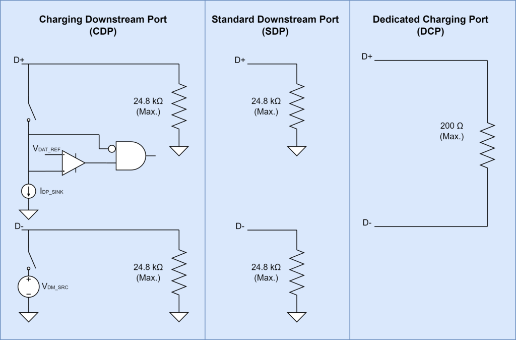
Figure 1 – USB BC 1.2 Ports
Standard Downstream Port (SDP)
This port incorporates pulldown resistors of 15 kΩ on data lines (D+/D-) as shown in Figure 1. The current limits are 2.5 mA when in suspended state, 100 mA when connected, and 500/900 mA when connected and configured for higher power in accordance with USB 2.0/3.0 specifications.
Dedicated Charging Port (DCP)
DCP exclusively provides power for battery charging purposes and lacks the ability to enumerate a downstream device. It does not facilitate data transfer, but it can supply current up to 1.5 A. Notably, it incorporates a short or a resistor up to 200 Ω between data lines. Dedicated charging ports are largely used in wall chargers and car chargers where data transfer is not required.
Charging Downstream Port (CDP)
This port offers both data transfer capability compliant with USB 2.0/USB 3.0 with faster charging. It includes pulldown resistors of 15 kΩ on data lines. In addition, there is an integrated internal circuitry which implements charger detection functionality that is activated during the charger detection phase. This internal setup enables sink devices to differentiate a CDP from other port types.
Charger Detection Process
The USB BC 1.2 Charger detection process involves several key stages illustrated in Figure 2.
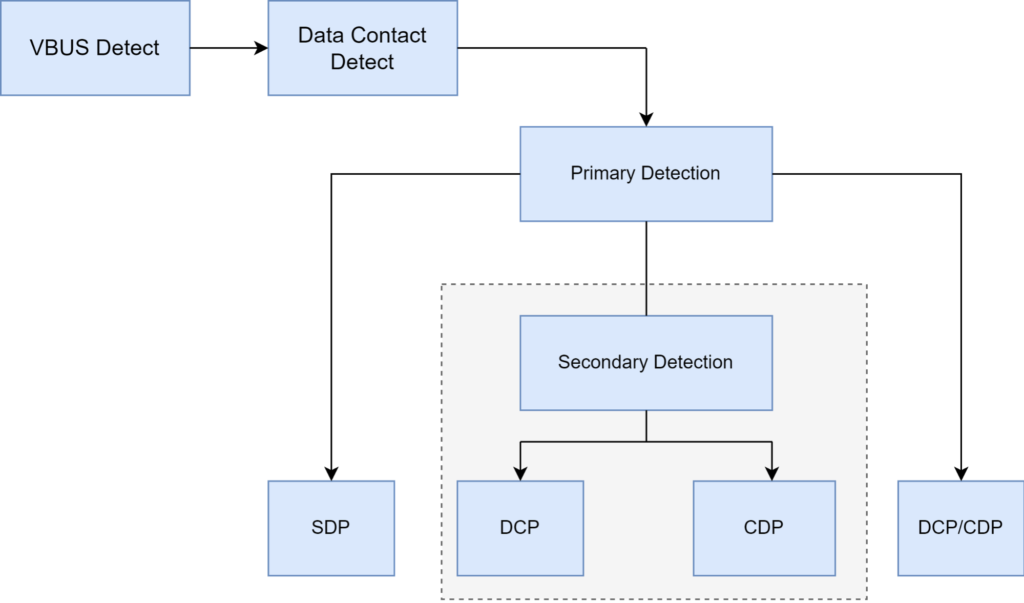
Figure 2 – USB BC 1.2 Detection Process
VBUS Detect
This phase is initiated by VBUS detection to ensure its presence. VBUS undergoes evaluation and is compared against a threshold voltage utilizing a session valid comparator embedded within the portable device. Once this detection process is successful, it confirms that the portable device is connected to a valid port.
Data Contact Detect (DCD)
After confirming the validity of VBUS voltage, the portable device must verify data pin contact before commencing any detection process. Premature decision by the end device before establishing contact with the data pins could lead to incorrect identification of the connected charger. This non-compulsory step confirms the establishment of data lines contact between the device and host port during attachment.
Primary Detection
At this stage, the end device distinguishes ports capable of delivering over 500/900 mA of current, labeled as CDP and DCP, from the port type with a current delivering capability of 500/900 mA, identified as SDP.
Secondary Detection
Secondary detection process verifies whether the BC1.2 charging port connected to the portable device supports USB data transmission (either DCP or CDP).
Conclusion
USB Battery Charging 1.2 stands as a significant advancement in USB charging standards, offering clear classifications for ports (SDP, DCP, and CDP) and detection processes that enhance charging for portable devices. Its adaptability, particularly in integrating with USB Type-C ports, demonstrates its compatibility with evolving technology. Overall, these specifications streamline charging processes, ensuring compatibility, and improving user experiences across a wide array of USB devices.
References
- USB-IF, Battery Charging Specification. Revision 1.2, December 7, 2010
- “A primer on USB Type-C and Power Delivery applications and requirements,” Nate Enos, Brian Gosselin, Texas Instruments, November 2016.
- “USB Battery Charging with the USB253x/USB46x4/ USB3x13 Hub Controllers” Arnaldo Cruz, Brigham Steele, and Connor Chilton, Microchip Technology, Inc.
- “Overview of USB Battery Charging Revision 1.2 and the Important Role of Charger Detectors” Mohamed Ismail, Analog Devices, Inc.