Introduction
Finite State Machines (FSMs) are fundamental building blocks used in digital designs. The FSMs enable designers to encapsulate complex logic into manageable, modular blocks. If it is used in a structured way, the FSM can enhance readability, maintainability, and scalability of digital designs. Among other applications, FSMs are used to control the sequence of operations in digital circuits, manage data flow, and implement protocol interfaces.
In this article we will be looking into some pitfalls and ways to prevent them when designing FSMs in VHDL. Whether you are a beginner or an experienced VHDL designer, understanding and mastering FSM design is key to creating robust, efficient, and scalable digital solutions.
FSM Basics
At the heart of FSMs lies the concept of states. A state represents a specific configuration or condition of the system, and the state machine can only be in one state at a time. Transitions between states are controlled by input signals or the current FSM state. The Input signals will have different effects, depending on the state. The FSM generates outputs or performs actions, making it an ideal tool for managing sequential processes and decision-making logic in digital circuits.
If the output is determined solely by the current state, the state machine is called a Moore machine.. This approach often simplifies the design, as the output is stable for the entire duration of the state. In a Mealy state machine, the output is influenced both by the current state and the input. This allows for more immediate reactions to input changes but can result in a more complex design. The choice between a Moore or a Mealy machine depends on the specific requirements of the digital system being designed.
FSM Planning
Before diving into the FSM design, iit is important to understand what the FSM is intended to accomplish and to clarify the process that the FSM is supposed to control. Use the information you have about the system to outline all the inputs that can be useful for the FSM and all outputs the FSM needs to generate to control the system. It is important to know the requirements for the outputs. Do they need to be glitch-free or are there any timing requirements from when an input changes to when the output needs to be updated? This will determine if you can use a Moore or Mealy type machine and what kind of state encoding you should select later. The next step is to identify the possible states for the FSM. Try to abstract the state to a level high enough, where a state represents a specific condition or situation the system can be in. Sometimes the analysis can result in a lot of possible states. If the FSM becomes too complex, it is recommended to see if any of the outputs are independent from the other outputs, and check if it is possible to simplify the FSM or split up the FSM into two or more FSMs. Doing a thorough analysis of the states and the timing of the inputs and outputs is important and worth the time, to prevent changes later. Giving unambiguous and describing names to the different states and input and output signals will make the design more understandable for others.
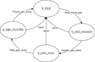
Based on the analysis it is possible to draw a state machine flow diagram that shows all states and all possible triggers and transitions between the different states. See the drawing above for an example. It is important to have well defined state transitions.
One- or two-process state machine
Since VHDL is a very flexible language, it is possible to implement an FSM in a wide variety of ways. For a designer it should be a goal to write VHDL code that is robust, error-resistant, and easy to understand and maintain. Writing the FSM in a structured and well-organized manner has many benefits. It will make the FSM recognizable to anyone, it will make it easier to update and it will make the FSM less error-prone.
Below is an example of a Single process FSM:
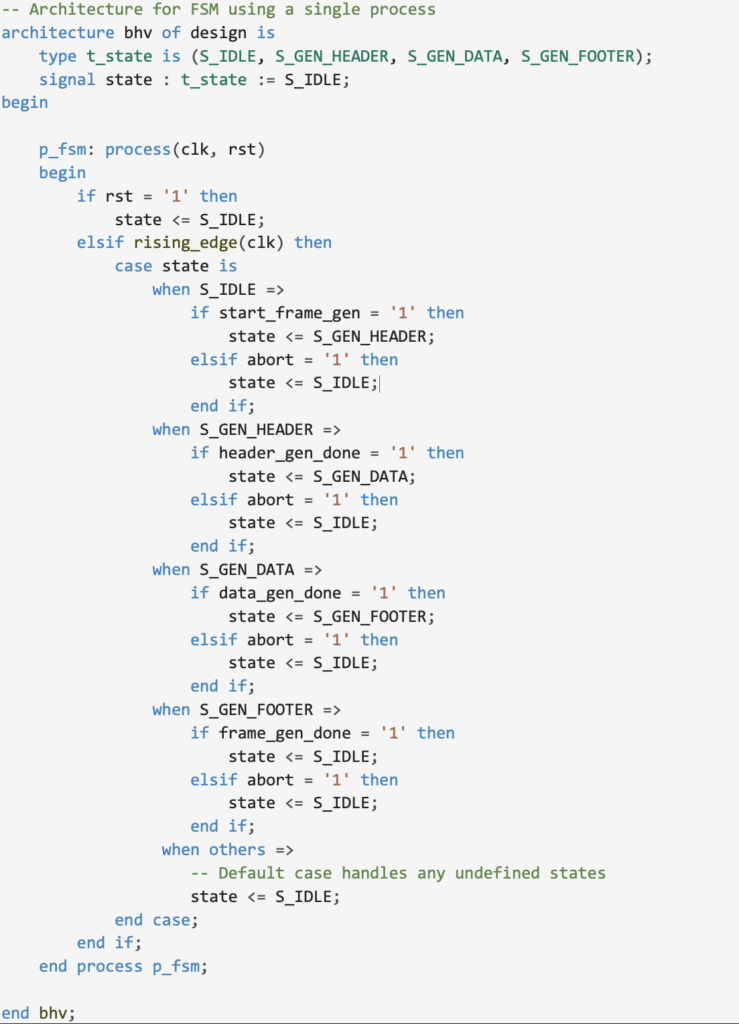
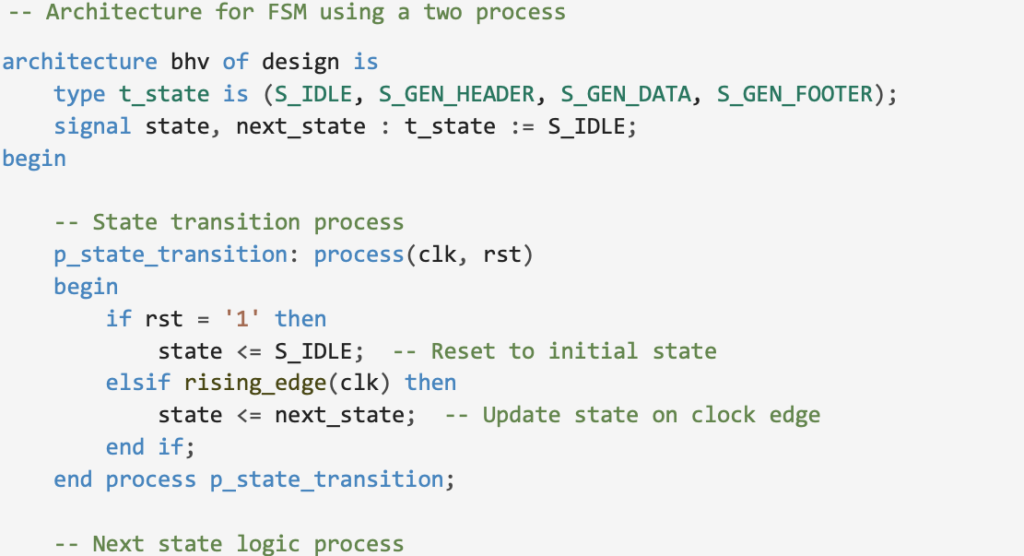
This is normally a sufficient solution when the FSM is quite simple like in the example. But it may become chaotic in cases where there are many states, state transitions and outputs to control. A way to handle more complex FSMs is to split the FSM into one process that contains the sequential registers for the states and one process that contains the combinatorial logic for the next state.
See example below.
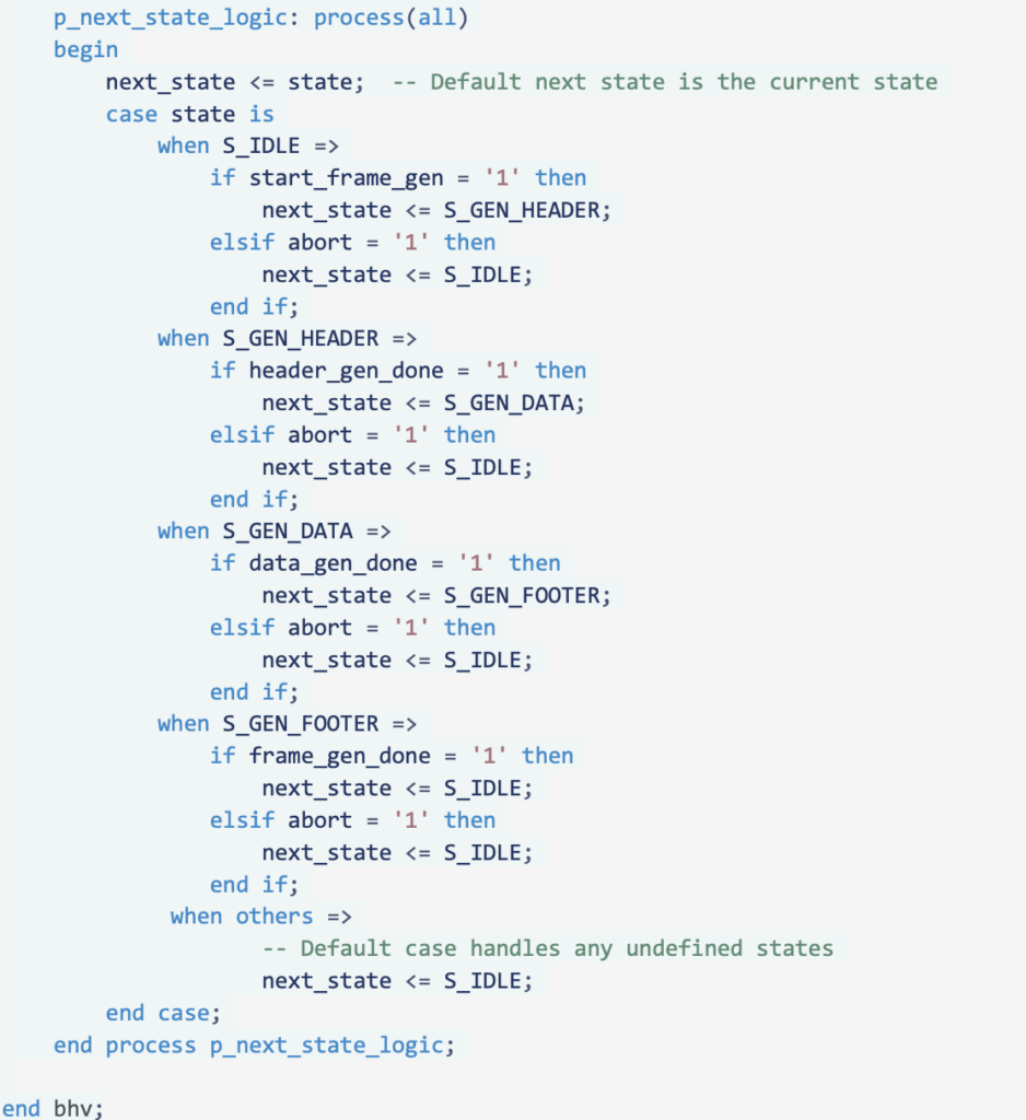
The control of the FSMs outputs can be put into either the sequential or combinatorial process depending on if it is a Moore or Mealy state machine. Alternatively, it may be added in a separate process for the outputs
Splitting the different parts of the FSM into multiple processes is also useful in designs where formal verification is used, because it makes it easier for the tools to evaluate and understand the functionality.
State encoding
Depending on system requirements and the application the FSM is going to control, there are different ways to encode the FSM states. The 3 most common ways to encode FSM states are:
Binary Encoding: States are encoded in the minimum number of bits needed to represent all states (log2(N) where N is the number of states). The FSM-states are assigned values between 0 and N without any special consideration.
- + This is the simplest and most resource efficient way to implement an FSM.
- – When transitioning between states, multiple bit transitions can cause glitches (temporarily going to another valid state when the different bits are switching). Glitches are only a problem if the state/outputs are used asynchronously.
– Propagation delay: In very high speed designs the combinational logic involved in the next state logic might slow down the speed.
One-hot Encoding: Each state is represented by one bit and the FSM is encoded so only one bit set at any time. The number of bits needed to One-hot encode an FSM is equal to the number of states.
- + Simple decoding and minimal propagation delay in next state logic.
- + Transition between states will never temporarily go through another valid state and is therefore more glitch resistant.
- + Single bit-flips always results in going to an invalid state.
- – Uses more resources because of the need for one bit per state.
Gray code Encoding: The states are encoded in such a way that any state transition only has one bit change at a time.
- + This encoding is Power efficient because of the minimal toggling of registers.
- + Because only one bit changes at each transition, it reduces the risk of glitches when changing states.
- – Gray coding can often result in complex transition logic and high propagation delay.
By default, binary encoding is used for an FSM, but it is possible to select other encodings by using tool dependent attributes added in the VHDL code or by synthesis constraints.
Examples of VHDL attributes for type of encoding:
Microchip / Lattice syntax:

Intel syntax:

AMD syntax:

How to handle undefined states
What is an undefined state? Depending on the state encoding and the number of states there might be undefined states. Example: An FSM has 5 states and uses binary encoding. This results in 3 registers needed to encode the 5 defined states, but also 3 undefined states. Or an FSM has 4 states and uses one-hot encoding. This results in 4 registers needed to encode the 4 defined states, but also 12 undefined states. What will happen if the FSM somehow (ex. electromagnetic noise, cosmic radiation, unstable power supply) gets into one of the undefined FSM states?
In the code examples above the VHDL code contains “when others => “ in the VHDL-case for the state machine, and for the dual process variant also an default next_state. This is good code practice and will define what happens if a state is left out in the VHDL-case, but it will not cover what happens if the FSM enters an undefined state. To define what should happen when an FSM enters an undefined state, you need to tell the synthesis tool to use “safe” FSM construction. This is done the same way as for the state encoding by tool dependent attributes or synthesis constraints.
VHDL attributes for safe state FSMs:
Intel / Microchip / Lattice syntax:

AMD syntax:

It is possible to tell the synthesis tool what state an undefined state should return to.
In some designs, it can be good idea to add an error state “S_ERROR” to your VHDL code that undefined states can return to. In the “S_ERROR” state the consequence of the error should be defined. It is important to get the entire system back to a state that we know is working. This could be done by resetting the system or flushing the data-path or just going back to an IDLE state.
Conclusion:
Effective planning and structured implementation of FSMs simplify the design and maintenance of complex systems. Employing safe state FSMs ensures robust handling of undefined states, enhancing system reliability and integrity.