Download this White Paper as PDF.
Circuit model
The first step in understanding the electrical operation of solar panels is to see how a single photovoltaic (PV) cell is modeled. This is presented in Figure 1, where the main elements are the current source and the diode, (more simplistic models omit the resistors altogether). The brighter and more orthogonally the sun shines on the cell, the more current. Some of that current will be diverted through the diode causing a voltage to build, whereas the rest can be delivered to a load.
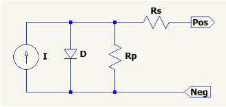
To get an idea of the magnitudes of the current and voltage developed, the maximum current of modern cells will typically be around 40 mA/cm2, at a voltage of about 0.55 V/cell at 25 °C. So the larger the cell, the more current can be delivered to a load, while the voltage is largely unaffected.
The output of a PV cell depends on the type of load it powers, and for visualisation of various conditions, you will commonly see IV curves like the plot presented in Figure 2. It is easily obtained by simulating the PV model with a voltage source on its output, running a DC sweep from 0 to ~0.7 V. By stepping the current source, we visualise the effect of varying light intensity, i.e. the power incident to the cell.
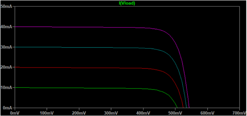
The slight reduction of current with increasing voltage is a measure of the undesirable leakage through the cell. It is modeled by the shunt resistor, and the smaller the resistance, the steeper the slope. Similarly, the losses from wiring is modeled by the series resistor, and its effect is to reduce the steepness of the curve to the right of the knee. Both effects contribute to decreasing efficiency of the cell, reducing how much power can be extracted at a given temperature. The short-circuit current Isc, (for which the voltage is zero), and the open-circuit voltage Voc, (for which there is no output current), are both given in data sheets. Typically values are stated at standard test conditions (STC), corresponding to an irradiance of 1 kW/m2 at 25 °C. The diode voltage exhibits a negative temperature coefficient, so with increasing temperature the knee of the curve moves to the left. At the same time the available current slightly increases, but this effect is almost an order of magnitude smaller. Hence solar cells should be kept cool to maximise power generation.
Power
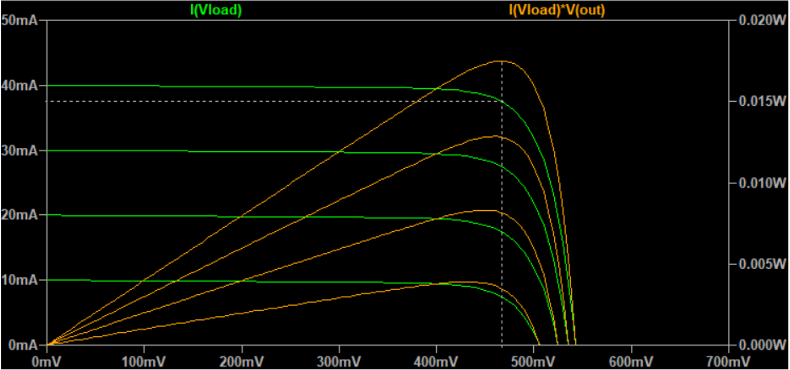
Since power is the product of current and voltage, we can deduce from the IV curves that with increasing load voltage, power scales linearly for any given current. This is shown in Figure 3, where the voltage for maximum power for the 40 mA case is marked with a vertical dotted line. This voltage, called Vmp, as well as the corresponding current Imp, are normally also stated at STC in data sheets.
In theory a solar panel could be directly connected to a battery for charging, as long as the battery voltage is below the maximum output voltage from the panel. While the sun is shining, the current source will drive current into the battery, and the voltage will be whatever the battery voltage is. But of course, we should follow the battery’s recommended charging algorithm to promote a long battery life, which is why PWM controllers were introduced to that application.
For larger installations, all the wasted power inherent in operating PV panels at voltages well below Vmp is not acceptable. To extract the maximum amount of power for any irradiance, we must ensure that the load is continuously matched to the PV module. Maintaining an optimum output voltage for any current is called maximum power point tracking (MPPT). Instead of a PWM controller we insert a DC/DC converter between the module and the load. But contrary to ordinary DC/DC converters which regulate the output voltage, the DC/DC converter of an MPPT controller will regulate its input voltage so as to maximise the power delivery.
Panel architecture
In order to raise the low voltage of a single PV cell to something more convenient, solar panels have a number of individual cells connected in series. As long as every cell is identical in size, and exposed to the same amount of sunlight, they each add their cell voltages while maintaining the current through the chain. But if a cell is shaded or degraded, for example due to micro-cracking, its current source is severely limited, and due to the series connection none of the cells will be able to deliver more than this low amount.
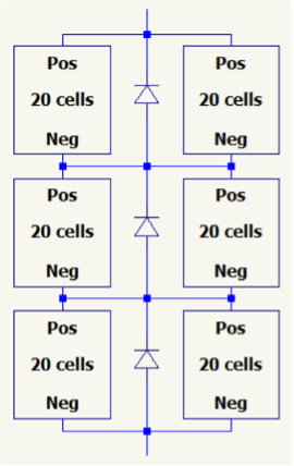
Referring to the electrical model in Figure 1, in the presence of current-blocking cells, all other cells in the string are forced to drive the excess amount of current through their own diodes, causing the cells to heat up. Thus, to spot the presence of defective cells, an IR camera can be used to observe local hot and cold spots of an evenly illuminated panel. To limit the total heat generation to safe levels, and allow the panel to produce more power while partly shaded, large panels split the string of cells into smaller groups. Each group usually consists of 18-24 series-connected cells, with a bypass diode in parallel with the string. When two or more such groups are series-connected, current from the non-shaded group can pass through the bypass diode of the shaded group. A common arrangement for panels of size 1-2 m2 is shown in Figure 4.
Over the years the size of individual PV cells has increased, and so the current level has increased too. When all that current is forced through a bypass diode due to partial shading of the panel, the voltage across the diode must be minimised to avoid extreme heat generation. Therefore the industry that started with PN diodes soon moved to schottky diodes, and some are now even transitioning to active diodes, (i.e. an active circuit emulating an ideal diode with zero voltage drop).
All bypass diodes are normally placed in a common enclosure called the junction box, usually located at the back of the panel. From this box also extend the cables for external connections, most often terminated in waterproof MC4 connectors or similar.
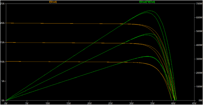
An interesting problem may arise when a panel is partly shaded, as illustrated in Figure 5. A model with parameters gathered from the datasheet of a commercially available panel has been simulated, the architecture is as given in Figure 4. All but one of the 20-cell groups are set to generate 5 A, while the last group is set to zero, half, or full production. We see that whenever partial shading occurs, the power curve may end up with multiple local maxima – and depending on the degree of shading, the global maximum power point might even be at the lower voltage. This poses a problem for MPPT controllers, necessitating implementation of a more complex algorithm.
Blocking diodes
When a panel is in the dark no current will be generated, but the diodes of the cells will still be present, and able to conduct reverse current. Thus, for loads such as a battery, a panel in the dark would slowly drain the charge unless we provide means to prevent the reverse current. This can be done by inserting a blocking diode between the panel and the battery, selected to appropriately handle the maximum day-time current. But in the case of battery charging with a PWM or MPPT controller, this unit normally includes the reverse blocking functionality.
In many cases, a single panel is not enough. Either because we need more power, or maybe we want coverage for multiple directions, as is often the case on moving objects such as a boat. The optimum solution to maximise power generation is then to provide each panel with a separate MPPT controller, but that is often prohibitively costly.
If the panels are mounted such that they will likely be exposed to the same lighting conditions, they could be wired in series, as long as the controller can handle the total voltage and power. But when conditions are very dissimilar, as will be the case if the panels point in totally different directions, only the panel with the greatest exposure to the sun will in fact contribute positively to power generation, (more on this further down). In that case it might be better to use a parallel configuration, provided that the controller can handle the total possible amount of current and power.
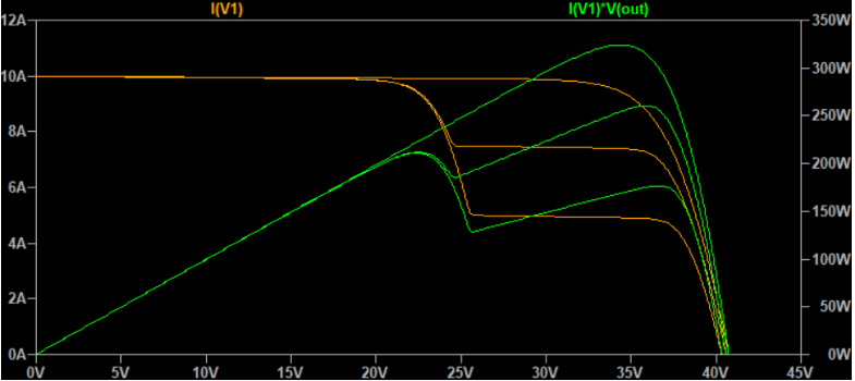
With panels in parallel, the question is again whether to use blocking diodes, to prevent panels pointing away from the sun from draining current from those that produce. The simulation result presented in Figure 6 shows the effect of such diodes for parallel panels in different lighting conditions, compared to simply shorting the panels directly. One panel is assumed to face the sun, generating 10 A. The other panel is assumed placed differently, generating 0.1, 5, or 10 A. In all cases maximum total power from the two panels is greater without the blocking diodes, although the difference is miniscule in the 0.1 A case.
The only situation in which blocking diodes actually help is when one panel is completely in the dark, but the difference is only about 1.5 W. Compared to the loss of the diodes in all other cases, (up to about 13 W in this simulation), we are normally better off avoiding blocking diodes altogether. From a functional perspective we maximise power, simplify installation, avoid heat generation from the diodes, and increase reliability of the system since fewer parts can fail.
Mixing different panels
Whenever multiple panels are connected to a single controller, they should be of the same size and type. Otherwise, if the panels are connected in series, the panel with the greatest current output will force excess current through the internal bypass diodes of all the smaller panels. Consequently there will be a voltage drop through each of those panels, and we will in fact obtain less power from the chain than from the large panel used by itself. This is the same situation as when series-connected identical panels are mounted to point in different directions.
The effect of connecting in parallel is a bit more complex, but Figure 7 illustrates the problem, whether we use blocking diodes or not. A small panel is in this case constructed of two series-connected strings of cells capable of 3 A, while a large panel is as depicted in Figure 4, with a current of 5 A per branch.
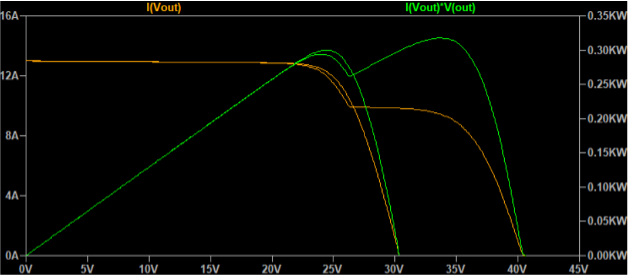
As long as the voltage is below the maximum power point of the smaller panel, both panels contribute to power generation. But an MPPT controller will drive the voltage to a power peak, and if there are no blocking diodes, the voltage of the smaller panel will be the maximum attainable, (see how the green curve with only one peak falls off beyond about 25 V).
When blocking diodes are present we obtain the green curve with two peaks, and an MPPT controller with a sufficiently advanced algorithm would set the voltage for the global maximum of the power curve. In this simulation that means about 33.5 V, for which we obtain 317 W. For comparison the large panel by itself produces 324 W, so again we would be better off with a single large panel pointed directly towards the sun.
One last note regarding panels in parallel: For safety we should always use a fuse per branch. Let’s say a strike of lightening has shorted all internal bypass diodes of a panel. The other panel would then drive all its current through the damaged panel, risking excessive heat to build, possibly causing a fire.