Electronics produce heat, and without proper management, this heat can break your components.
Thermal management basically comes down to two components: thermal detectors (sensors) and cooling devices. Linux provides a framework, where you can specify the mapping of thermal detector events to cooling devices’ responses.
In this article we will take a look at the Raspberry Pi 5, to see how the thermal management is handled there, but the setup will be pretty similar between all devices.
In Linux, a “thermal zone” refers to a region within a system that is monitored for temperature changes. The kernel uses thermal zones to manage and monitor the temperatures of different components, such as the CPU, GPU, or other hardware sensors that may be critical to the system’s operation.
For the Raspberry Pi 5, it is quite a small system, so only has one thermal management zone defined:
					thermal-zones {
	cpu_thermal: cpu-thermal {
		polling-delay-passive = <1000>;
		polling-delay = <1000>;
		coefficients = <(-550) 450000>;
		thermal-sensors = <&thermal>;

		thermal_trips: trips {
			cpu_crit: cpu-crit {
				temperature	= <110000>;
				hysteresis	= <0>;
				type		= "critical";
			};
		};

		cooling_maps: cooling-maps {
		};
	};
};
Link to source: bcm2712.dtsi
This thermal zone – as the name suggests – handles the thermal management of the CPU (in this case a BCM2712 chip).
thermal-sensors:
This is where you can define the sensors which are used to monitor the temperature of the thermal zone. We will look at the implementation of this after.
thermal-trips:
These are definitions of temperature “events“ which will trigger an action. For now, only a “critical“ trip type is defined, which means reaching this trip point (110°C = 110_000 m°C) will lead to critical system failure if not addressed (e.g. chip melting). A trip point of this type will send a signal to the thermal core to shutdown the chip.
cooling_maps:
This is where you can define the mapping of thermal events (trips) and the corresponding response to that event.
As we can see, this thermal zone definition is quite sparsely populated. This is because this is the device tree include file for the CPU only (BCM2712). Systems like the Raspberry Pi 5 contain more than a CPU, so it is in its device tree file that most of the temperature mappings between components are defined.
If we look at the
thermal-sensors
field, we see it references the label
thermal:
					thermal: thermal {
	compatible = "brcm,bcm2711-thermal";
	#thermal-sensor-cells = <0>;
};
Link to source: bcm2712.dtsi
This still is in the bcm2712 device tree include, since it must be a temperature sensor integrated in the CPU package.
Following the compatible string, we can find the driver for this temperature sensor. We will look into the drivers for the different thermal zone components a bit later.
Now if we take a look at the device tree for the Raspberry Pi 5 board, we can see the thermal trips have been expanded:
					&thermal_trips {
	cpu_tepid: cpu-tepid {
		temperature = <50000>;
		hysteresis = <5000>;
		type = "active";
	};

	cpu_warm: cpu-warm {
		temperature = <60000>;
		hysteresis = <5000>;
		type = "active";
	};

	cpu_hot: cpu-hot {
		temperature = <67500>;
		hysteresis = <5000>;
		type = "active";
	};

	cpu_vhot: cpu-vhot {
		temperature = <75000>;
		hysteresis = <5000>;
		type = "active";
	};
};
Link to source: bcm2712-rpi-5-b.dts
Here we can see some different trip points at different temperatures (given in milli degrees Celsius). The
hysteresis
field is used to define how long the cooling response triggered at a temperature trip point is maintained. For
cpu-vhot,
a cooling response will be triggered at 75°C. This cooling response will be in effect until the temperature is below 70°C (
temperature
–
hysteresis).
Also in the device tree source for the Raspberry Pi 5, we can see the
cooling_maps
node has been populated:
					&cooling_maps {
	tepid {
		trip = <&cpu_tepid>;
		cooling-device = <&fan 1 1>;
	};

	warm {
		trip = <&cpu_warm>;
		cooling-device = <&fan 2 2>;
	};

	hot {
		trip = <&cpu_hot>;
		cooling-device = <&fan 3 3>;
	};

	vhot {
		trip = <&cpu_vhot>;
		cooling-device = <&fan 4 4>;
	};

	melt {
		trip = <&cpu_crit>;
		cooling-device = <&fan 4 4>;
	};
};
Link to source: bcm2712-rpi-5-b.dts
Here we can see how the temperature trips shown above relate to responses with cooling devices. Taking the example from earlier with
cpu_vhot,
if the temperature goes over 75°C, this will trigger the response:
cooling-device = <&fan 4 4>;.
This response will be active until the hysteresis level is met (70°C in the example above).
It is important to note that cooling responses are split into two categories, active and passive. Active cooling is when you activate a device like a fan to remove heat. Passive cooling regulates device performance in order to produce less heat. For example, techniques like thermal throttling exist where you will reduce the clock frequency of your CPU dynamically to reduce the heat it produces and therefore the temperature.
The final part of the device tree puzzle, this is where you specify your device that does the cooling – either active or passive.
					fan: cooling_fan {
	status = "disabled";
	compatible = "pwm-fan";
	#cooling-cells = <2>;
	cooling-min-state = <0>;
	cooling-max-state = <3>;
	cooling-levels = <0 75 125 175 250>;
	pwms = <&rp1_pwm1 3 41566 PWM_POLARITY_INVERTED>;
	rpm-regmap = <&rp1_pwm1>;
	rpm-offset = <0x3c>;
};
Link to source: bcm2712-rpi-5-b.dts
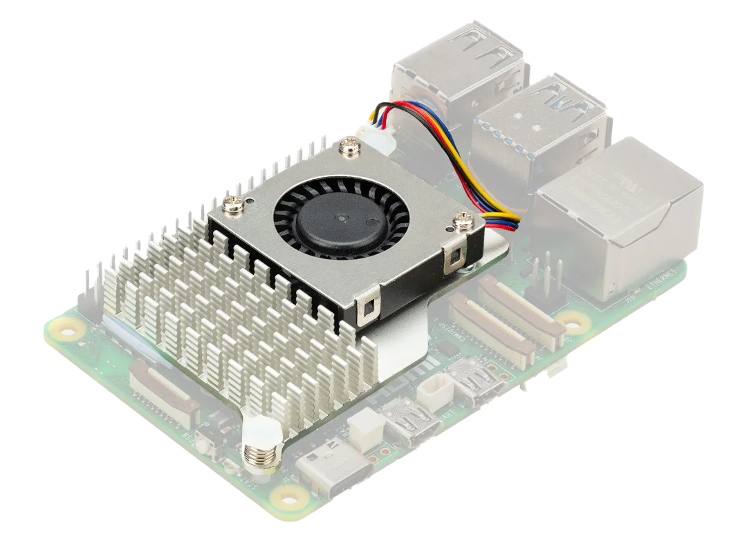
In the case of the Raspberry Pi 5, the cooling device is the fan shown in the picture. The device tree node specifies different cooling levels (fan speeds), which can be called on different temperature trip points. For example, at 50°C (
cpu_tepid),
the fan is activated at level 1 (
cooling-device = <&fan 1 1>;).
At 60°C (
cpu_warm)
the fan is activated at level 2 (
cooling-device = <&fan 2 2>;).
We see also that the fan uses the driver with the
compatible = "pwm-fan";
string.
cooling-min-state and cooling-max-state are not actually used in the driver implementation,
only cooling-levels is, which is why we have possible cooling levels from 0 → 4
Some good documentation sources describing the different components of thermal-zones and their device-tree bindings (descriptions of all the fields in the device tree nodes) can be found in the Documentation folder of the kernel:
pwm-fan (used by the Raspberry Pi 5 fan)
You can view and interact with devices related to the thermal framework through the
/sys
filesystem. You can navigate to
/sys/class/thermal/
to see what is there.

We can see for the Raspberry Pi 5, we have one cooling device (corresponding to the fan), and one thermal zone (corresponding to the CPU thermal zone).
You can, for example, change the state of the cooling device by writing to its
cur_state
file. If you have a Raspberry Pi 5 to hand it is quite fun to watch the fan go different speeds.
In the thermal zone, you can check the reading from the temperature sensor from the
temp
file. For fun, try turning on the fan and watch the effect on the temperature.
All of this device tree information needs to be connected somehow, and this is done with a number of kernel drivers/modules.
There are a number of core thermal modules which are responsible for connecting the different components of the thermal framework. A couple of these include:
In essence, sensors and cooling devices are registered with these core modules, and these modules manage the connection between devices, according to how it is in arranged in the device tree.
One function for helping this happen is the
static struct device_node *of_thermal_zone_find(struct device_node *sensor, int id)
function, which searches for the
thermal-zones
node in the device tree, in order to get the connection information and configurations for the thermal framework. This is called when the
thermal_of_zone_register
function is called, which we see in the temperature sensor driver example below.
As we saw earlier, the temperature sensor driver used for the Raspberry Pi 5 is the one with the compatible string:
.compatible = "brcm,bcm2711-thermal".
Searching for this string, we see that the
bcm2711_thermal
kernel module is used for this.
Link to source: bcm2711_thermal.c
The driver works as a platform device, and registers the device with the thermal core, using:
					struct thermal_zone_device *thermal = devm_thermal_of_zone_register(dev, 0, priv,
                                                                    &bcm2711_thermal_of_ops);
During this registration, it defines some thermal operations that the temperature sensor is capable of. In this case, a
get_temp
callback is defined.
					static int bcm2711_get_temp(struct thermal_zone_device *tz, int *temp)
{
	struct bcm2711_thermal_priv *priv = thermal_zone_device_priv(tz);
	int slope = thermal_zone_get_slope(tz);
	int offset = thermal_zone_get_offset(tz);
	u32 val;
	int ret;

	ret = regmap_read(priv->regmap, AVS_RO_TEMP_STATUS, &val);
	if (ret)
		return ret;

	if (!(val & AVS_RO_TEMP_STATUS_VALID_MSK))
		return -EIO;

	val &= AVS_RO_TEMP_STATUS_DATA_MSK;

	/* Convert a HW code to a temperature reading (millidegree celsius) */
	*temp = slope * val + offset;

	return 0;
}

static const struct thermal_zone_device_ops bcm2711_thermal_of_ops = {
	.get_temp	= bcm2711_get_temp,
};
For the Raspberry Pi 5, the cooling fan uses the
.compatible = "pwm-fan"
connected driver.
Link to source: pwm-fan.c
Here again, we can see the cooling device getting registered with the thermal core:
					cdev = devm_thermal_of_cooling_device_register(dev,
			dev->of_node, "pwm-fan", ctx, &pwm_fan_cooling_ops);
This specifies a list of thermal operations, which are connected to callback functions:
					static const struct thermal_cooling_device_ops pwm_fan_cooling_ops = {
	.get_max_state = pwm_fan_get_max_state,
	.get_cur_state = pwm_fan_get_cur_state,
	.set_cur_state = pwm_fan_set_cur_state,
};
As we have seen, there is already an established thermal core, so typically you will be writing either cooling device or temperature sensor drivers. In a nutshell, all that needs to be done is to register the device with the thermal core, and implement the callbacks for the required thermal operations.
Raspberry Pi has some good documentation on how to build and configure your kernel here: Linux Kernel
Obviously it can be quite hard to physically raise the temperature of your thermal zone to test that the correct cooling device responses are being triggered. The get around this, the thermal framework has a nice feature that lets you emulate the temperature of a thermal zone.
By enabling the kernel config
CONFIG_THERMAL_EMULATION,
you will get a new attribute in your sysfs node corresponding to the thermal zone. This attribute is
emul_temp
and you can write emulated temperatures to it to see if the correct cooling responses are triggered. When you are done with testing, you can write
0
to the attribute to disable the temperature emulation, and go back to monitoring the temperature from the actual temperature sensor.
There are a few ways you can enable this build configuration. One way is to set
CONFIG_THERMAL_EMULATION=y
in your .config file, or if you use
menuconfig
it can be set in Device Drivers -> Thermal Drivers -> Thermal emulation mode support.
You can then build your kernel, and play around with the emulated temperature in
/sys/class/thermal/thermal_zone0/emul_temp.