When it comes to learning Embedded Linux, the Raspberry Pi is one of the most accessible systems on the market. The Raspberry Pi offers some neat advantages to a user who wants to start learning Embedded Linux. Along with good documentation, the Raspberry Pi also has an exposed set of I/O (input/output) pins on a pin header, which makes it ideal for interfacing with different devices while learning e.g. LEDs or I2C devices. The fact that it is fully separate system from your main PC allows you a risk free playground for trying out new things.
Launched in 2023, the Raspberry Pi 5 boasts significant performance upgrades over previous models, making it a likely option for starting Embedded Linux learning.
In this article we will focus on how you can use the Raspberry Pi 5 with your GPIO drivers, a basic starting point for learning how linux drivers work. The main focus here will be on the specifics of the Raspberry Pi 5 platform needed when writing GPIO drivers, and not as in depth on general driver concepts.
The OS used for the Raspberry Pi was the “Raspberry Pi OS (64-bit)“ downloaded from the Raspberry Pi software page.
Previously, numbers were used to identify GPIOs in kernel drivers. This has now been deprecated in favor of identifiers in the form of descriptors (in the form of
struct gpio_desc).
This provides several advantages over the integer identifiers, including a more obvious mapping between the GPIO you are describing and the hardware GPIO that is used.
This new API contains functions with the naming
gpiod_.
Some examples of these functions include:
					void gpiod_set_value(struct gpio_desc *desc, int value);
int gpiod_set_debounce(struct gpio_desc *desc, unsigned int debounce);
For getting the desired
struct gpio_desc,
we can use a number of functions, including this one:
struct gpio_desc *gpiod_get(struct device *dev, const char *con_id, enum gpiod_flags flags);
Using the device tree to define your device properties, such as GPIO, is good practice. This avoids hard-coding device properties into drivers, and makes your device driver configuration agnostic. Let’s take a look at using the device tree on the Raspberry Pi 5.
The first thing to do is to identify which device tree files your kernel is using. These files can be accessed from the kernel source for Raspberry Pi.
In the case of the Raspberry Pi 5, it is using the Broadcom BCM2712, so this is the file you will want to find.
If newer versions of Raspberry Pi 5 are released, they might use a different chip set
We can find the device tree source (.dts) file in
arch/arm64/boot/dts/broadcom/bcm2712-rpi-5-b.dts.
This is where the root node of the device tree is defined, and is where we will add our GPIO device node.
One way of adding a device node to the device tree is using the device tree overlay functionality. This is basically a way of adding or overriding properties/nodes of the device tree you are targeting.
Here is an example of a device tree overlay you might use for defining a GPIO node:
					/dts-v1/;
/plugin/;

/* Defines GPIO_ACTIVE_LOW */
#include "/usr/src/linux-headers-6.6.31+rpt-common-rpi/include/dt-bindings/gpio/gpio.h"

/ {
	compatible = "brcm,bcm2712";
	fragment@0 {
		target-path = "/";
		__overlay__ {
			demo-led {
				compatible = "emlogic,demo-gpio-driver";
				led-gpios = <&rp1_gpio 13 GPIO_ACTIVE_LOW>;
			};
		};
	};
};
compatible = "brcm,bcm2712";
This indicates which device tree source we want to overlay. As we can see in the
bcm2712-rpi-5-b.dts
file, the compatible string is
compatible = "raspberrypi,5-model-b", "brcm,bcm2712";.
This means our overlay will match with this device tree.
target-path = "/";
This specifies that the overlay modifications will occur on the root node of the device tree
compatible = "emlogic,demo-gpio-driver";
This is where we specify which driver/drivers the device is compatible with. When this device is loaded in the device tree, the driver with the matching compatible string will be loaded. We want this to match our driver.
led-gpio = <&rp1_gpio 13 GPIO_ACTIVE_LOW>;
This specifies which GPIO we are going to use. The naming in the format
<function>-gpios = ...
is very deliberate, and this is what the
gpiod_get
function uses to identify which GPIO description to use. This is useful when you have a device using multiple GPIOs, since you can distinguish between them in the driver.
We can see we are using GPIO number 13 (GPIO13) from the
rp1_gpio
chip. The Raspberry Pi 5 has a number of GPIO chips which can be selected in the device tree, e.g.
gio_aon, rp1_gpio…
You have to find out which GPIO chip your desired GPIO is connected to, and what its node label is in the device tree, so you can reference it. New for the Raspberry Pi 5, it has a dedicated I/O controlling chip called the RP1, which is connected to the pins on the breakout header.
Now we have our device tree overlay, we can compile it and overlay it to our device tree. Compiling will produce a
.dtbo
file, which we can overlay using the
dtoverlay
command.
					sudo dtoverlay demoled.dtbo

dtoverlay -l
Here is an example of how you might compile the device tree overlay:
					cpp -P demoled.dts -o demoled_preprocessed.dts
dtc -@ -I dts -O dtb -o demoled.dtbo demoled_preprocessed.dts
Since we have a
#include
in our device tree overlay file, we should run a pre-processor on it to resolve the
GPIO_ACTIVE_LOW.
We can then compile the device tree binary from this pre-processed file.
In the device tree overlay we use the header:#include "/usr/src/linux-headers-6.6.31+rpt-common-rpi/include/dt-bindings/gpio/gpio.h".
You can find which one your system is using by running something like:find /usr/src -wholename "*/dt-bindings/gpio/gpio.h".
If no kernel headers are present, you might have to install them with something like:sudo apt install raspberrypi-kernel-headers
When the compatible string in a device tree node matches that of a driver, the driver’s probe function will be called.
In the probe function, you can call a function like the following to get your
struct gpio_desc,
which then you can use in
gpiod
functions.
					static int dt_probe(struct platform_device *pdev) {
	struct device *dev = &pdev->dev;
    struct gpio_desc * my_led = gpiod_get(dev, "led", GPIOD_OUT_HIGH);
...
Here we can see the
con_id
(
"led"
) matches the
<function>-gpios
(
led-gpios
) naming we had in our device tree overlay.
Now we have the descriptor, we can use functions to interact with our LED:
					...
struct gpio_desc * my_led = gpiod_get(dev, "led", GPIOD_OUT_HIGH);

/* Sets the raw/physical state of the GPIO */
gpiod_set_raw_value(my_led, 0);
/* Gets the physical state of the GPIO */
int raw_value = gpiod_get_raw_value(my_led);

/* Sets the GPIO value, taking into account the line property:
 * Since we have a line property of "GPIO_ACTIVE_LOW" (see device tree overlay),
 * setting it to 1 will set the line active, with a physical
 * pin state of 0/low
 */
gpiod_set_value(my_led, 1);
/* Gets the GPIO value, taking into account line property */
int value = gpiod_get_value(my_led);
You can find the truth table of how these GPIO functions are working with different line properties in the kernel documentation: Documentation/driver-api/gpio/consumer.rst
There are a set of legacy GPIO functions – used in linux drivers – which use a GPIO number (assigned to each GPIO in the system) as an identifier. Some examples include:
					/* request GPIO, returning 0 or negative errno.
 * non-null labels may be useful for diagnostics.
 */
int gpio_request(unsigned gpio, const char *label);

/* release previously-claimed GPIO */
void gpio_free(unsigned gpio);

/* GPIO INPUT:  return zero or nonzero */
int gpio_get_value(unsigned gpio);

/* GPIO OUTPUT */
void gpio_set_value(unsigned gpio, int value);
While these functions are legacy, they are often taught as a first starting point for GPIO drivers, and might still be present in older drivers, so they are useful to know about. However, for new drivers the descriptor based identifiers described above should be used.
In previous versions of the Raspberry Pi, the mapping of GPIO<n> (n is the GPIO number on the pin header) was pretty direct to the GPIO numbers that would be used in the
unsigned gpio
argument of the GPIO functions. On the Raspberry Pi 5, the pin mapping works a bit differently.
First you will want to identify which GPIO pin you want to use on your header. Running the command
pinout
on your Raspberry Pi will show a nice graphic of the header pins and their names and function.
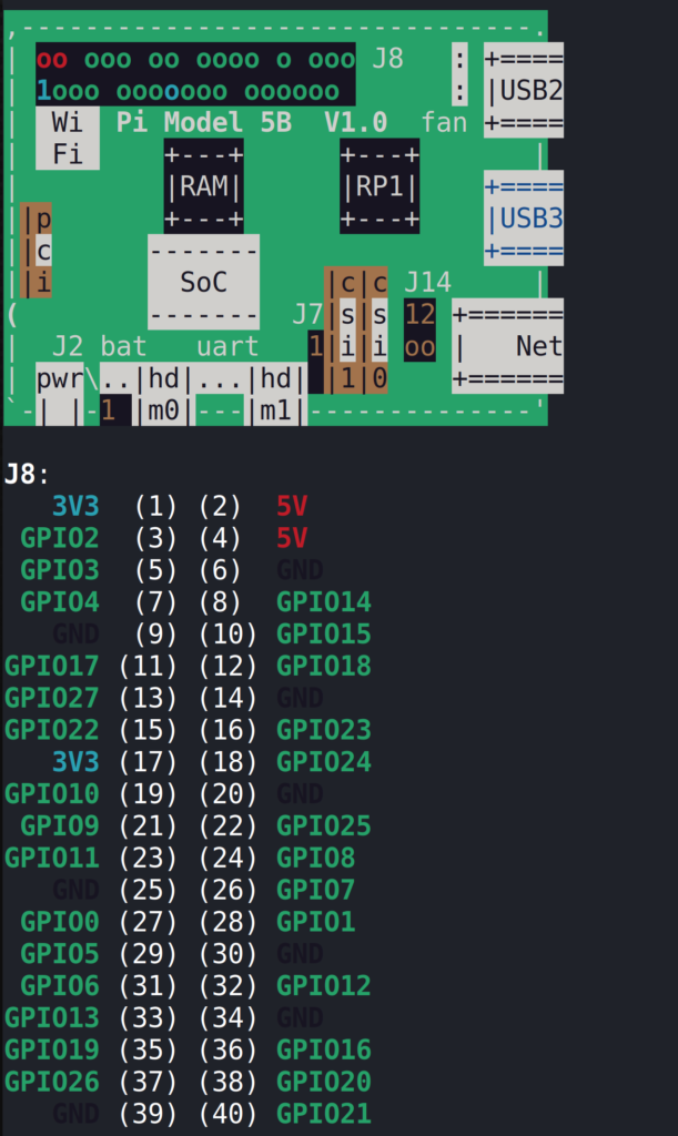
In the examples, GPIO13 is used.
With the desired GPIO, you can run the gpioinfo command which will print information about the lines of the GPIO chips. Here you can find which gpiochip you are using, and also which line on the chip your GPIO is connected to. For the case of GPIO13, this is gpiochip4, line 13.
					$ gpioinfo
...
gpiochip4 - 54 lines:
	line   0:     "ID_SDA"       unused   input  active-high
	line   1:     "ID_SCL"       unused   input  active-high
	line   2:      "GPIO2"       unused   input  active-high
	line   3:      "GPIO3"       unused   input  active-high
	line   4:      "GPIO4"       unused   input  active-high
	line   5:      "GPIO5"       unused   input  active-high
	line   6:      "GPIO6"       unused   input  active-high
	line   7:      "GPIO7"       unused   input  active-high
	line   8:      "GPIO8"       unused   input  active-high
	line   9:      "GPIO9"       unused   input  active-high
	line  10:     "GPIO10"       unused   input  active-high
	line  11:     "GPIO11"       unused   input  active-high
	line  12:     "GPIO12"       unused   input  active-high
	line  13:     "GPIO13"       unused   input  active-high
	line  14:     "GPIO14"       unused   input  active-high
	line  15:     "GPIO15"       unused   input  active-high
...
Now we know the gpiochip, we can find the GPIO number. The number of the GPIO is given by a base number given to each gpiochip, added to the line number on that gpiochip.
Running the command cat /sys/kernel/debug/gpio will display a list of these derived GPIO numbers.
					$ cat /sys/kernel/debug/gpio
...
gpiochip4: GPIOs 571-624, parent: platform/1f000d0000.gpio, pinctrl-rp1:
 gpio-571 (ID_SDA              )
 gpio-572 (ID_SCL              )
 gpio-573 (GPIO2               )
 gpio-574 (GPIO3               )
 gpio-575 (GPIO4               )
 gpio-576 (GPIO5               )
 gpio-577 (GPIO6               )
 gpio-578 (GPIO7               )
 gpio-579 (GPIO8               )
 gpio-580 (GPIO9               )
 gpio-581 (GPIO10              )
 gpio-582 (GPIO11              )
 gpio-583 (GPIO12              )
 gpio-584 (GPIO13              )
 gpio-585 (GPIO14              )
 gpio-586 (GPIO15              )
...
Depending on which configuration options your kernel is built with, this file may or may not exist.
However, using the “Raspberry Pi OS (64-bit)“ from the Raspberry Pi software page, this is available in the kernel.
Here we can see our gpiochip4 has a base number of 571. Therefore GPIO13 – which is line 13 on this chip – is 571 + 13 = 584.
Now we know our GPIO number, we can use it to access the GPIO, using the unsigned gpio function argument.
There also exists a
/sys
filesystem ABI (Application Binary Interface) for controlling GPIOs. This is also deprecated but still present on many systems. It also makes use of GPIO numbers so is interesting to look at.
Running
ls /sys/class/gpio
will show an output like shown below. Here we can see the gpiochips listed, including our gpiochip4 (with base number 571). We also have these export and unexport files.

Output from ls /sys/class/gpio
If we write our desired GPIO number to the export file, we will get access to a directory which allows us to control the GPIO from the filesystem. To do this you need to use the GPIO number we found earlier.
Running
echo 584 > export
will create a new folder named gpio584 (assuming the GPIO is not currently used by the system), which inside it will have the following options:

Files inside the gpio584 folder
Here you can read the pin direction withcat direction, and set it to either in or out by writing to the direction file
(e.g. echo out > direction). You also read the GPIO value with the value file, and if set in output mode you can set the GPIO value by writing to the value file (e.g. echo 1 > value).
When you no longer need the GPIO, you can unexport it by writing to the unexport file in /sys/class/gpio
(e.g. echo 584 > unexport).
In this article, we have explored a bit the use of GPIO functions, and their legacy counterparts. The recommended
gpiod_
functions provide a much nicer mapping between the GPIO being described and the hardware GPIO being used, leading to nicer interfaces and less chance for errors.
We have also looked at some Raspberry Pi 5 implementation specifics for using the device tree to describe the GPIO you want to use, and also how you can find GPIO numbers if you are using the legacy functions.
One recommendation for learning linux drivers through examples is this Youtube series by Johannes 4GNU_Linux.
In the series, a Raspberry Pi 3 model is used, so sometimes some slight adjustments are needed for working on the Raspberry Pi 5,
like with the GPIO examples.